

Xinghe Da Technology Co., Ltd
Contacts:Jack Peng
Mobile:+86 18627553022
Whatsapp:+86 18627553022
WeChat: pengyi-changsha
E-mail:admin@chinaxingheda.com
Company address :2506 Xidi Building, No. 8 Fenglin Third Road, Yuelu District, Changsha City, Hunan Province
OLT,XPON-HUAWEI AUX SL91 Auxiliary interface board
Version Description
The functional version of the AUX is SL91
Functions and Features
The AUX provides the system with one orderwire phone port, one synchronous data port, one asynchronous data port, and one four-input two-output external alarm port
Table 1 lists the functions and features that the AUX supports
Table 1 Functions and features
Product Details:
Version Description
The functional version of the AUX is SL91.
Functions and Features
The AUX provides the system with one orderwire phone port, one synchronous data port, one asynchronous data port, and one four-input/two-output external alarm port.
Table 1 lists the functions and features that the AUX supports.
Table 1 Functions and features
Working Principle
The AUX consists of the orderwire unit, logic control unit, and clock unit.
Functional Block Diagram
Figure 1 Functional block diagram of the AUX
Power Supply Unit
Receives the +3.3 V power supply from the backplane and supplies it to the other units on the AUX.
Receives and shuts down control signals.
Orderwire Unit
Supports the input of four channels of alarms.
Supports the output of two channels of alarms.
Provides one orderwire port.
Provides one 64 kbit/s synchronous transparent data port.
Provides one 19.2 kbit/s asynchronous transparent data port.
NOTE:
The 64 kbit/s synchronous data port can transparently transmit orderwire byte. One port, however, can implement only one of the two functions: 64 kbit/s synchronous data port and transparent transmission of orderwire byte.
Logic Control Unit
Provides an interface with the CPU unit and works with the CPU unit to implement the board control function.
Processes orderwire bytes and overhead bytes.
Processes clock signals.
Provides board status information.
Checks the status of the system control, switching, and timing board.
Checks the status of the clock.
Supports the switching of system clock reference sources automatically and by running specific commands.
Supports the detection and reporting of the key clock status of each board in the system.
Board Status Detection Unit
Detects board performance data such as board voltage.
Stores board manufacturing information.
Clock Unit
Provides clock signals to the logic control unit.
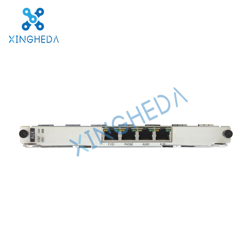
Front Panel
There are indicators, management ports, and auxiliary ports on the front panel.
Front Panel Diagram
Figure 1 shows the appearance of the front panel of the AUX.
Figure 1 Front panel of the AUX
Indicators
Table 1 Status explanation for indicators on the AUX
Auxiliary Ports and Management Ports
Table 2 Description of the auxiliary ports and management ports
The auxiliary ports and management ports use RJ45 connectors. The pin assignments for the ports, however, are different. Figure 2 shows the front view of an RJ45 connector.
Figure 2 Front view of an RJ45 connector
Table 3 provides the pin assignments for the F1/S1 port.
Table 3 Pin assignments for the F1/S1 port
For the pin assignments for the ALMI and ALMO ports, see Table 4 and see Table 5.
Table 4 Pin assignments for the ALMI port
Table 5 Pin assignments for the ALMO port
External alarms are also called housekeeping alarms or relay alarms. OptiX RTN 910A provides external alarms.
Figure 3 shows an interface circuit for external alarm input. When the relay of the external system is switched off, the IDU interface circuit detects a high-level signal. When the relay of the external system is switched on, the IDU interface circuit detects a low-level signal. The board generates corresponding alarms based on the level signals detected by the IDU interface circuit. External alarm input mainly achieves access of the relay alarms generated by the environmental alarm generator.
Figure 3 Interface circuit for external alarm input
Figure 4 shows an interface circuit for external alarm output. When the external alarm output conditions are met, the equipment switches on or off the relay depending on the conditions that result in the alarm. External alarm output helps to provide equipment alarms to the centralized alarming device.
The functional version of the AUX is SL91.
Functions and Features
The AUX provides the system with one orderwire phone port, one synchronous data port, one asynchronous data port, and one four-input/two-output external alarm port.
Table 1 lists the functions and features that the AUX supports.
Table 1 Functions and features
| Function and Feature | Description |
| Orderwire phone port | 1 |
| Synchronous data port | 1 The port transmission rate is 64 kbit/s and its specifications comply with ITU-T G.703. |
| Asynchronous data port | 1 The transmission rate of the port is equal to or less than 19.2 kbit/s and the interfacing level complies with RS-232. |
| External alarm port | Four inputs and two outputs |
| Hot swapping | Supported |
| Queries of the board power consumption | Supported |
| Power monitoring | Supported |
Working Principle
The AUX consists of the orderwire unit, logic control unit, and clock unit.
Functional Block Diagram
Figure 1 Functional block diagram of the AUX
Power Supply Unit
Receives the +3.3 V power supply from the backplane and supplies it to the other units on the AUX.
Receives and shuts down control signals.
Orderwire Unit
Supports the input of four channels of alarms.
Supports the output of two channels of alarms.
Provides one orderwire port.
Provides one 64 kbit/s synchronous transparent data port.
Provides one 19.2 kbit/s asynchronous transparent data port.
NOTE:
The 64 kbit/s synchronous data port can transparently transmit orderwire byte. One port, however, can implement only one of the two functions: 64 kbit/s synchronous data port and transparent transmission of orderwire byte.
Logic Control Unit
Provides an interface with the CPU unit and works with the CPU unit to implement the board control function.
Processes orderwire bytes and overhead bytes.
Processes clock signals.
Provides board status information.
Checks the status of the system control, switching, and timing board.
Checks the status of the clock.
Supports the switching of system clock reference sources automatically and by running specific commands.
Supports the detection and reporting of the key clock status of each board in the system.
Board Status Detection Unit
Detects board performance data such as board voltage.
Stores board manufacturing information.
Clock Unit
Provides clock signals to the logic control unit.
Front Panel
There are indicators, management ports, and auxiliary ports on the front panel.
Front Panel Diagram
Figure 1 shows the appearance of the front panel of the AUX.
Figure 1 Front panel of the AUX
Indicators
Table 1 Status explanation for indicators on the AUX
| Indicator | State | Meaning |
| STAT | On (green) | The board is working properly. |
| On (red) | The board hardware is faulty. | |
| Off | The board is not working. The board is not created. There is no power supplied to the board. |
|
| SRV | On (green) | The system is working properly. |
| On (red) | A critical or major alarm occurs in the system. | |
| On (yellow) | A minor or remote alarm occurs in the system. | |
| Off | There is no power supplied to the system. |
Table 2 Description of the auxiliary ports and management ports
| Port | Description | Connector Type |
| F1/S1 | Synchronous/Asynchronous data port | RJ45 |
| ALMI | Alarm input port | |
| ALMO | Alarm output port | |
| PHONE | Orderwire phone port |
Figure 2 Front view of an RJ45 connector
Table 3 provides the pin assignments for the F1/S1 port.
Table 3 Pin assignments for the F1/S1 port
| Port | Pin | Signal |
| F1/S1 | 1 | Transmitting asynchronous data signals |
| 2 | Grounding end | |
| 3 | Receiving asynchronous data signals | |
| 4 | Transmitting synchronous data signals (TIP) | |
| 5 | Transmitting synchronous data signals (RING) | |
| 6 | Grounding end | |
| 7 | Receiving synchronous data signals (TIP) | |
| 8 | Receiving synchronous data signals (RING) |
Table 4 Pin assignments for the ALMI port
| Port | Pin | Signal |
| ALMI | 1 | The first external alarm input signal |
| 2 | Grounding end for the first external alarm input signal | |
| 3 | The second external alarm input signal | |
| 4 | The third external alarm input signal | |
| 5 | Grounding end for the third external alarm input signal | |
| 6 | Grounding end for the second external alarm input signal | |
| 7 | The forth external alarm input signal | |
| 8 | Grounding end for the forth external alarm input signal |
| Port | Pin | Signal |
| ALMO | 1 | The first external alarm output signal (+) |
| 2 | The first external alarm output signal (-) | |
| 3 | The second external alarm output signal (+) | |
| 4 | Connected in parallel with pin 1 | |
| 5 | Connected in parallel with pin 2 | |
| 6 | The second external alarm output signal (-) | |
| 7 | Connected in parallel with pin 3 | |
| 8 | Connected in parallel with pin 6 |
Figure 3 shows an interface circuit for external alarm input. When the relay of the external system is switched off, the IDU interface circuit detects a high-level signal. When the relay of the external system is switched on, the IDU interface circuit detects a low-level signal. The board generates corresponding alarms based on the level signals detected by the IDU interface circuit. External alarm input mainly achieves access of the relay alarms generated by the environmental alarm generator.
Figure 3 Interface circuit for external alarm input
Figure 4 shows an interface circuit for external alarm output. When the external alarm output conditions are met, the equipment switches on or off the relay depending on the conditions that result in the alarm. External alarm output helps to provide equipment alarms to the centralized alarming device.
A Free Consultation
You can contact us any way that is convenient for you. We are available 24/7 via fax, email or telephone.