

Xinghe Da Technology Co., Ltd
Contacts:Jack Peng
Mobile:+86 18627553022
Whatsapp:+86 18627553022
WeChat: pengyi-changsha
E-mail:admin@chinaxingheda.com
Company address :2506 Xidi Building, No. 8 Fenglin Third Road, Yuelu District, Changsha City, Hunan Province
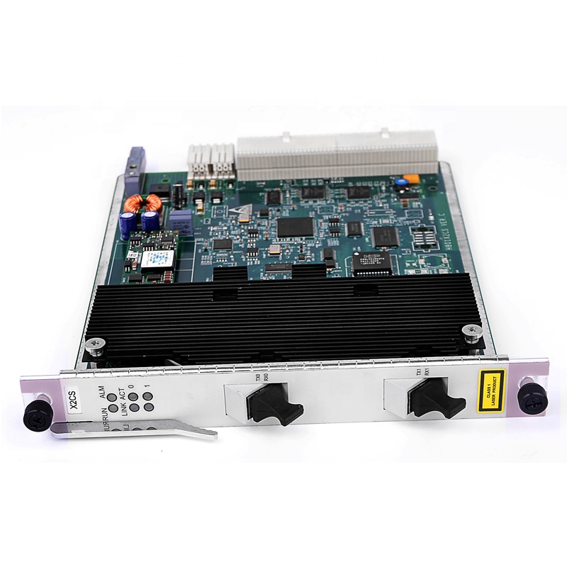
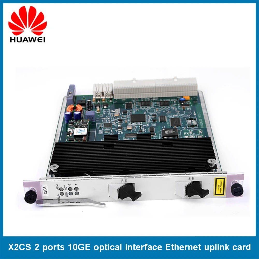
Original Huawei X2CS 10G Uplink OLT Card for Huawei MA5680T MA5683T MA5608T OLT, Including 2 Pieces of 10G Uplink Module
Xingheda Technology Co , Ltd provides Huawei OLT machine or board, such as MA5600T, MA5603T, MA5608T, etc If you have specific model requirements, please contact us, thank you
Product Details:
Overview
The H801X2CS board supports the following functions:
- Two 10GE upstream ports
- 10GE synchronous Ethernet
Figure 1 External connections of the H801X2CS board
Working Principle
Figure 2 Working principle of the H801X2CS board
The basic working principle of the H801X2CS board is as follows:
- The control module reports the status and manufacture information about the board, and provides interface information. The control module also manages other functional modules on the board and processes alarms.
- The interface module provides two 10GE ports.
- The synchronous Ethernet clock module extracts clock signals from the 10GE signals and synchronizes the 8 kHz clock of the control board with the clock signals.
- The power module supplies power to other functional modules of the board.
- The clock module provides clock signals for other functional modules of the board.
Front Panel
Table 1 Front panel of the H801X2CS board
|
RUN: running status indicator |
||
|
Green: blinks every 1s |
The board is functioning properly. |
|
|
Green: blinks every 0.25s |
The board is starting up. |
|
|
ALM: alarm indicator |
||
|
Red: on |
The board is faulty. |
|
|
Red: off |
The board is functioning properly. |
|
|
LINK: optical fiber connection indicator |
||
|
Green: on |
The connection of the optical fiber is normal. |
|
|
Green: off |
The connection of the optical fiber is abnormal. |
|
|
ACT: service running indicator |
||
|
Yellow: blinks |
Data is being transmitted. |
|
|
Yellow: off |
No data is being transmitted. |
|
Port
The ports of the H801X2CS board are located on its front panel. Table 2 describes the ports of the H801X2CS board
Table 2 Ports of the H801X2CS board
|
Port |
Function |
Connection |
|---|---|---|
|
10GE optical ports |
Transmit two channels of 10GE signals upstream. |
Use an optical fiber to connect the port to the upper-layer device or the cascaded device. |
Specifications
Table 4 Specifications of the H801X2CS board
|
Board |
Dimensions (W x D x H) |
Power Consumption |
|---|---|---|
|
H801X2CS |
|
|
Pictures
A Free Consultation
You can contact us any way that is convenient for you. We are available 24/7 via fax, email or telephone.