

Xinghe Da Technology Co., Ltd
Contacts:Jack Peng
Mobile:+86 18627553022
Whatsapp:+86 18627553022
WeChat: pengyi-changsha
E-mail:admin@chinaxingheda.com
Company address :2506 Xidi Building, No. 8 Fenglin Third Road, Yuelu District, Changsha City, Hunan Province
OLT,XPON-HUAWEI OptiX RTN 910 Split-structured IP microwave transmission IDU equipment
Product Description
Network Application
The OptiX RTN 910 is microwave equipment deployed at the access layer Figure 1 shows the microwave transmission solution provided by the OptiX RTN 910
Figure 1 Microwave transmission solution provided by the OptiX RTN 910
NOTE:
The OptiX RTN 910 provides a wide range of inte
Product Details:
Product Description
Network Application
The OptiX RTN 910 is microwave equipment deployed at the access layer. Figure 1 shows the microwave transmission solution provided by the OptiX RTN 910.
Figure 1 Microwave transmission solution provided by the OptiX RTN 910
NOTE:
The OptiX RTN 910 provides a wide range of interfaces and service bearer technologies to adapt to the regional backhaul network. The regional backhaul network can be a time-division multiplexing (TDM) network or packet switching network (PSN).
The OptiX RTN 910 supports the Ethernet over SDH (EoSDH) function, Ethernet over PDH (EoPDH) function, and ML-PPP function. Therefore, packet services can be backhauled through a TDM network.
The OptiX RTN 910 supports the pseudo wire emulation edge-to-edge (PWE3) technology. Therefore, TDM, ATM, and Ethernet services can be backhauled through a PSN.
The OptiX RTN 910 supports the VLAN sub-interface function. Therefore, MPLS packet services can be backhauled through a Layer 2 network.
When three or more microwave directions are required, cascade several sets of the OptiX RTN 910 or use the OptiX RTN 950/950A/980 that provides more powerful functions and supports more microwave directions.
Components
The OptiX RTN 910 adopts a split structure. The system consists of the IDU 910 and the ODU. Each ODU is connected to the IDU 910 through an IF cable.
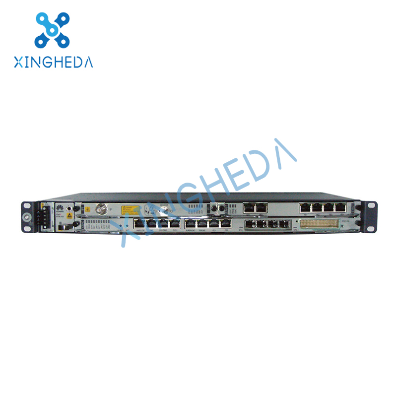
IDU 910
The IDU 910 is the indoor unit for an OptiX RTN 910 system. It receives and multiplexes services, performs service processing and IF processing, and provides the system control and communications function.
Table 1 lists the basic features of the IDU 910.
Table 1 Features of the IDU 910
Network Application
The OptiX RTN 910 is microwave equipment deployed at the access layer. Figure 1 shows the microwave transmission solution provided by the OptiX RTN 910.
Figure 1 Microwave transmission solution provided by the OptiX RTN 910
NOTE:
The OptiX RTN 910 provides a wide range of interfaces and service bearer technologies to adapt to the regional backhaul network. The regional backhaul network can be a time-division multiplexing (TDM) network or packet switching network (PSN).
The OptiX RTN 910 supports the Ethernet over SDH (EoSDH) function, Ethernet over PDH (EoPDH) function, and ML-PPP function. Therefore, packet services can be backhauled through a TDM network.
The OptiX RTN 910 supports the pseudo wire emulation edge-to-edge (PWE3) technology. Therefore, TDM, ATM, and Ethernet services can be backhauled through a PSN.
The OptiX RTN 910 supports the VLAN sub-interface function. Therefore, MPLS packet services can be backhauled through a Layer 2 network.
When three or more microwave directions are required, cascade several sets of the OptiX RTN 910 or use the OptiX RTN 950/950A/980 that provides more powerful functions and supports more microwave directions.
Components
The OptiX RTN 910 adopts a split structure. The system consists of the IDU 910 and the ODU. Each ODU is connected to the IDU 910 through an IF cable.
IDU 910
The IDU 910 is the indoor unit for an OptiX RTN 910 system. It receives and multiplexes services, performs service processing and IF processing, and provides the system control and communications function.
Table 1 lists the basic features of the IDU 910.
Table 1 Features of the IDU 910
| Item | Description |
| Chassis height | 1U |
| Pluggable | Supported |
| Number of radio directions | 1 or 2 |
| RF configuration mode | 1+0 non-protection configuration 2+0 non-protection configuration 2x(1+0) non-protection configuration 1+1 protection configuration N+1 protection configuration (N = 1) XPIC configuration |
| Service interface type | E1 interface STM-1 optical/electrical interface FE optical/electrical interface GE optical/electrical interface |
A Free Consultation
You can contact us any way that is convenient for you. We are available 24/7 via fax, email or telephone.