

Xinghe Da Technology Co., Ltd
Contacts:Jack Peng
Mobile:+86 18627553022
Whatsapp:+86 18627553022
WeChat: pengyi-changsha
E-mail:admin@chinaxingheda.com
Company address :2506 Xidi Building, No. 8 Fenglin Third Road, Yuelu District, Changsha City, Hunan Province
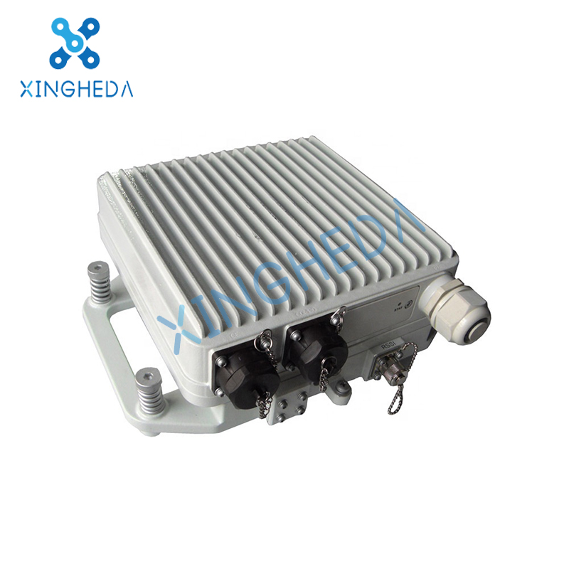
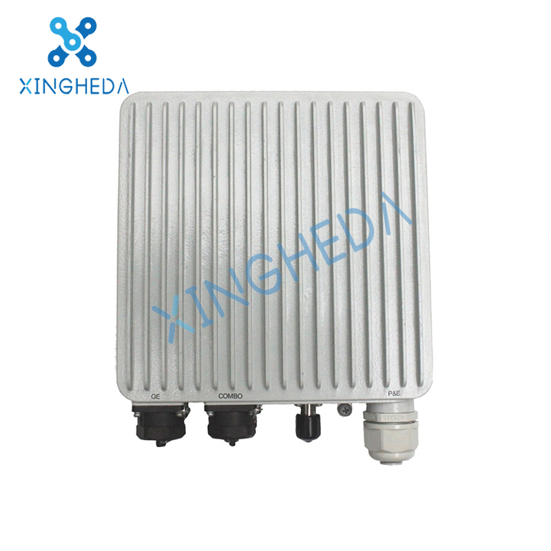
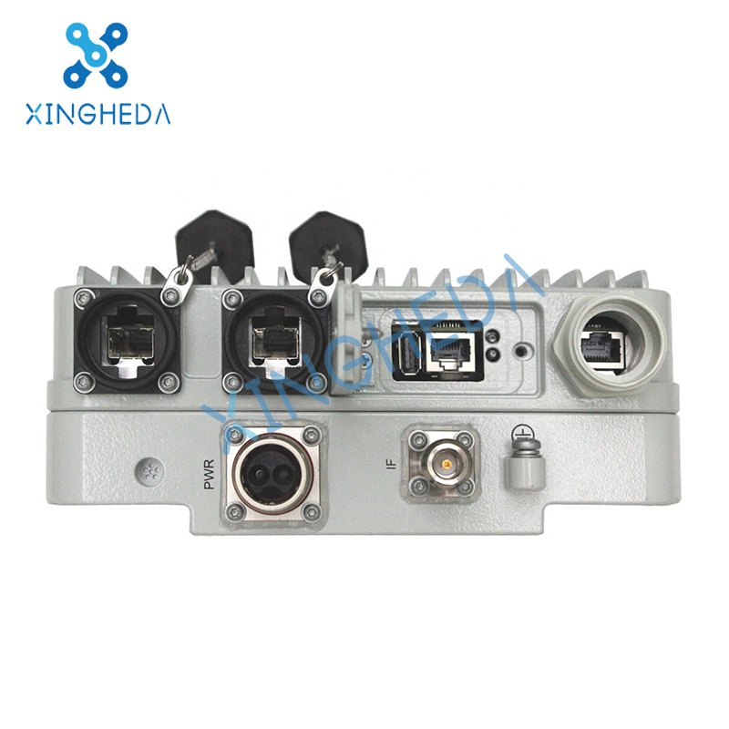
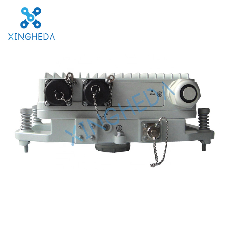
OLT,XPON-HUAWEI OptiX RTN 310 outdoor IP Microwave transmission IDU equipment
Product Description
Positioning
The RTN 310 is used to provide transmission solutions with low network construction cost for mobile communication networks and private networks
Compared with the traditional split microwave equipment, the RTN 310 integrates all its functions in an outdoor chassis, thereby implementing zero footprint installation Therefore, the RTN 310 can provide carriers with full-outdoor radio transmission solutions with low network construction cost and
Product Details:
Product Description
Positioning
The RTN 310 is used to provide transmission solutions with low network construction cost for mobile communication networks and private networks.
Compared with the traditional split microwave equipment, the RTN 310 integrates all its functions in an outdoor chassis, thereby implementing zero footprint installation. Therefore, the RTN 310 can provide carriers with full-outdoor radio transmission solutions with low network construction cost and operating expense.
The RTN 310 supports flexible networking. RTN 310s can form ring or chain backhaul networks for various IP base stations on existing or new networks.
The RTN 310 supports 2048QAM, XPIC, PLA, and 1+1 HSB/FD/SD. It can provide high-bandwidth backhaul links for high-capacity 3G/LTE base stations.
The main RTN 310 applications on mobile communication networks are as follows:
RTN 310 independently form tree or ring backhaul networks to provide links with high capacity, bandwidth, and reliability for 3G/LTE base stations. See Figure 1.
The RTN 310 works with the existing OptiX RTN 900 to provide multi-directional aggregation sites and more functions. See Figure 2.
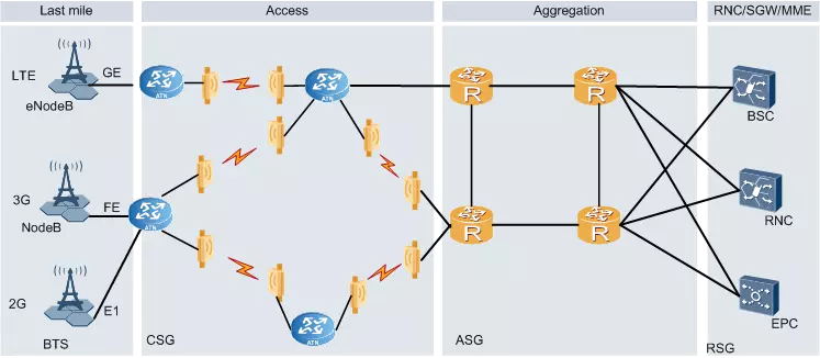
The RTN 310 works with the ATN to provide a microwave channel solution for transparent transmission on the IP RAN. See Figure 3.
Figure 1 Independent networking of RTN 310s
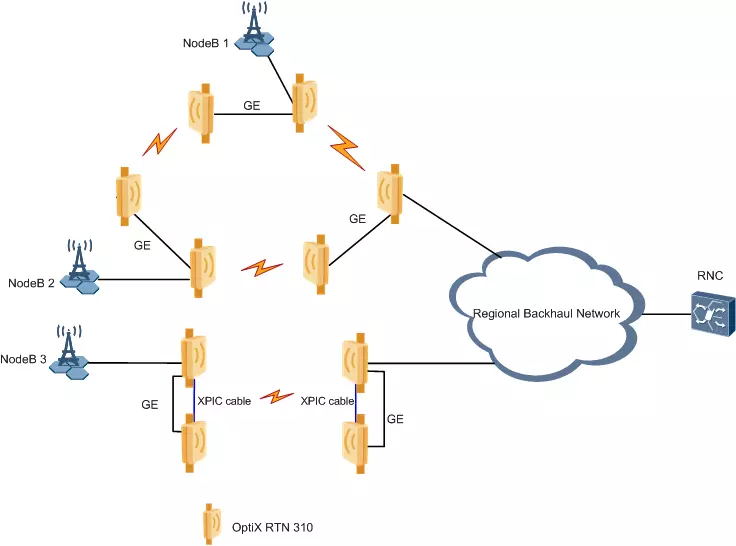
Figure 2 RTN 310 working with the OptiX RTN 900
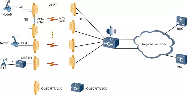
Figure 3 RTN 310 working with the ATN
Specifications
The RTN 310's specifications meet the requirements of mobile backhaul and private network backhaul.
Table 1 lists the main specifications of the RTN 310.
Table 1 Main specifications of the RTN 310
| Item | Specifications |
| Microwave type | IP microwave over native Ethernet and over PWE3 Ethernet |
| Frequency bands | 7/8/11/13/15/18/23/26/28/32/38 GHz |
| Channel spacings | 7/14/28/40/56 MHz |
| Modulation schemes | QPSK Strong/QPSK/16QAM Strong/16QAM/32QAM/64QAM/128QAM/256QAM/512QAM/512QAM Light/1024QAM/1024QAM Light/2048QAM NOTE: The difference between strong/light modulation schemes and normal modulation schemes lies in FEC encoding parameters. Strong modulation schemes have stronger error correction capabilities, which means higher receiver sensitivity but lower air interface bandwidth. Light modulation schemes have poorer error correction capabilities, which result in lower receiver sensitivity but higher air interface bandwidth. |
| Capacity | Maximum air capacity: 500 Mbit/s Maximum air-interface service throughput: 1.5 Gbit/s Maximum switching capacity: 8 Gbit/s |
| RF configuration modes | 1+0 configuration 2+0 configuration 1+1 HSB/FD/SD configuration Multi-directional site configuration XPIC configuration |
| Channel configuration modes | ACAP ACCP CCDP |
| AM | Supported |
| ATPC | Supported |
| Ethernet frame header compression | Supported |
| PLA | Supported |
| LLDP | Supported |
| Service ports | Two FE/GE SFP ports One GE electrical port, which provides the Power over Ethernet (P&E) function |
| Service types | Native Ethernet services: E-Line service and E-LAN service PW-carried Ethernet services: E-Line service, E-Aggr service, and E-LAN (VPLS) service (VPLS standing for virtual private LAN service) |
| QoS/HQoS | Supported |
| MPLS tunnel | Supported |
| PWE3 | Supported |
| Clock features | Supported clock sources: Microwave link clock Synchronous Ethernet clock IEEE 1588v2 time synchronization ITU-T G.8275.1 time synchronization |
| Power supply modes | Power over Ethernet (power supply through the PI or other specified power supply equipment) |
| Chassis dimensions (H x W x D) | 7/8/11 GHz: 210 mm x 210 mm x 92.7 mm 13/15/18/23/26/28/32/38 GHz: 210 mm x 210 mm x 90 mm |
| Antenna | Single-polarized antennas and dual-polarized antennas with a diameter of 0.3 m to 1.2 m as well as the corresponding antenna feeder accessories |
A Free Consultation
You can contact us any way that is convenient for you. We are available 24/7 via fax, email or telephone.